Select menu Meshes → Create Mesh from Shape.Open the FreeCAD file containing the lego piece.Let's convert one of the objects we modelled in the previous chapters, such as the lego piece (which can be downloaded from the end of the previous chapter).This workbench allows you to handle them fully in FreeCAD. Although working with meshes is not the focus of FreeCAD, when working with 3D modeling, you often need to deal with mesh objects, since their use is very widespread among other applications. This workbench contains, in addition to the most important tools that convert between Part and Mesh objects, several utilities meant to analyze and repair meshes. We need to check that the degradation stays within acceptable limits.Īll the mesh handling, in FreeCAD, is done by another specific workbench, the Mesh Workbench. All we need to be careful about, is that it is here that the degradation we mentioned above will occur. Fortunately, as much as converting a mesh to a solid is a complicated operation, the contrary, converting a solid to a mesh, is very straightforward.

So we will need to convert any object we want to 3D print into a mesh first, that the slicer can open. None of the slicers will, at this time, directly take the solid geometry as we produce in FreeCAD.
Ultimaker cura tutorial how to#
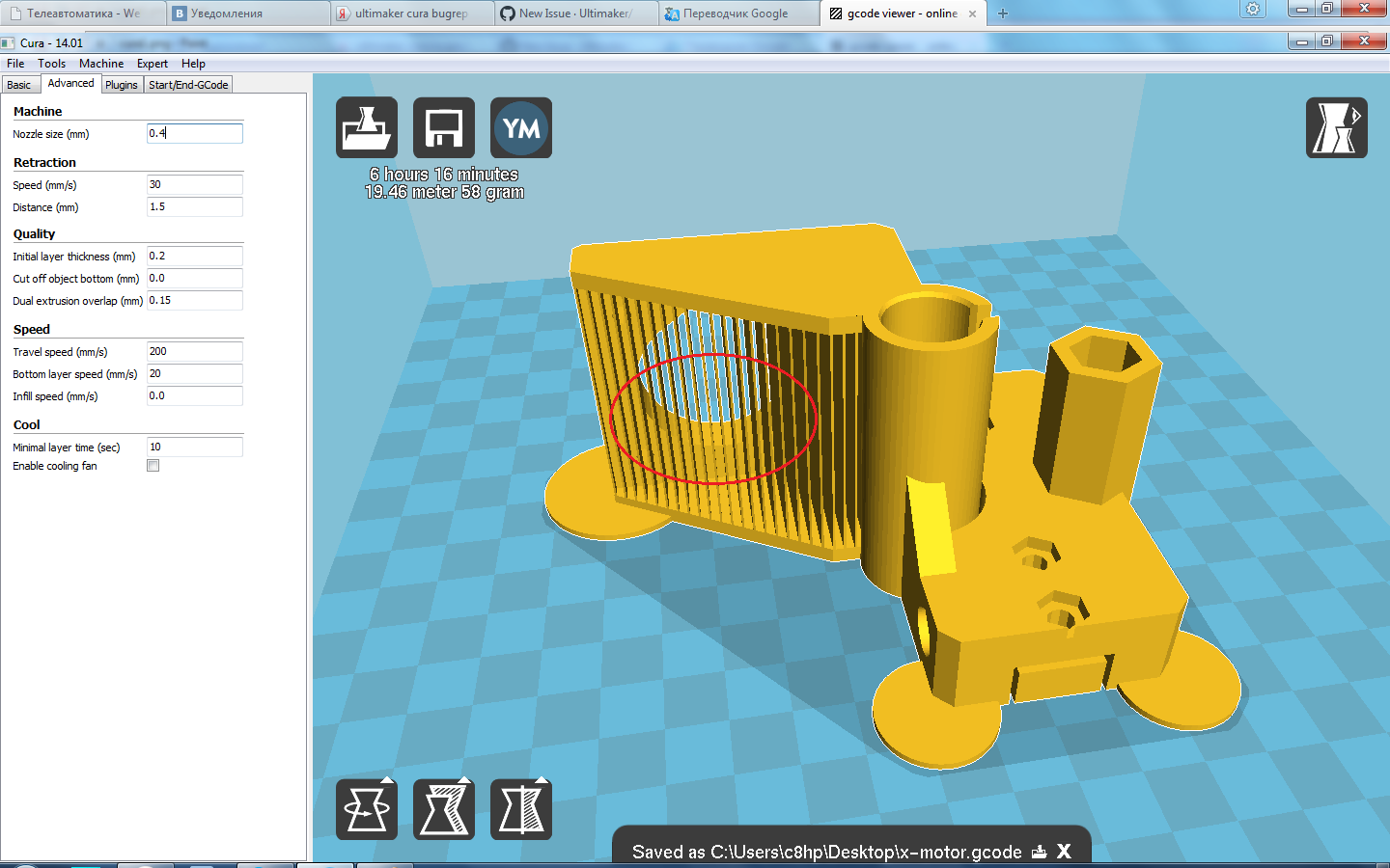
But we will see how to export and use these slicers to check that the output is correct. These programs usually offer advanced configuration possibilities that allow you to tailor the output exactly for the features of your 3D printer.Īctual 3D printing, however, is too vast a subject for this manual. Since many of those printers are home-built, there are often small differences from one to the other. The 3D object is exported to another program (the slicer) which will generate the G-code from the object, by slicing it into thin layers (hence the name), which will reproduce the movements that the 3D printer will do. This is the technique most commonly used for 3D printing. We will now see how to address the third point. When printing in 3D, you must always make sure this loss of quality stays below your minimum requirements.īelow, we will assume that the first two criteria are met, and that by now you are able to produce solid objects with correct dimensions. In any case, some loss of quality of your model will unavoidably occur during the process. The conversion of your models into G-Code can be easy and automatic, but you can also do it manually, with total control over the output. G-code has dozens of different dialects, each machine or vendor usually has its own. Most of them will only understand a machine language called G-Code. No 3D printing or CNC milling system can take FreeCAD files directly.

One millimeter will be one millimeter in real-life.

The Part Workbench also contains a Check Geometry tool that is handy to check further for possible defects. We saw in earlier chapters that FreeCAD helps you a lot in that regard, and that the PartDesign Workbench will notify you if you do an operation that prevents your model to stay solid. Real-world objects are solid, the 3D model must be solid too.


 0 kommentar(er)
